How Diffs Work – Mechanical Adding Machines
Hi boys and girls. It is my pleasure to talk about diffs today. What are diffs? They are wonderful creatures in the mecheng kingdom. Known by their full, technical name: differential gears, or more correctly, differentials. If you’ve ever witnessed one, they may seem to behave rather magically. Here’s why.
Conventional Gears
Before looking at diffs, let’s first look at spur gears. Spur gears have some properties which are interesting despite being rather obvious.
Gears couple the mechanical rotation of multiple axles. That’s a fancy way of saying that if two axles are geared together, like that shown in the figure below, then the axle’s rotation are directly linked with each other. A rotation of one axle will definitely imply the rotation of the other axle.
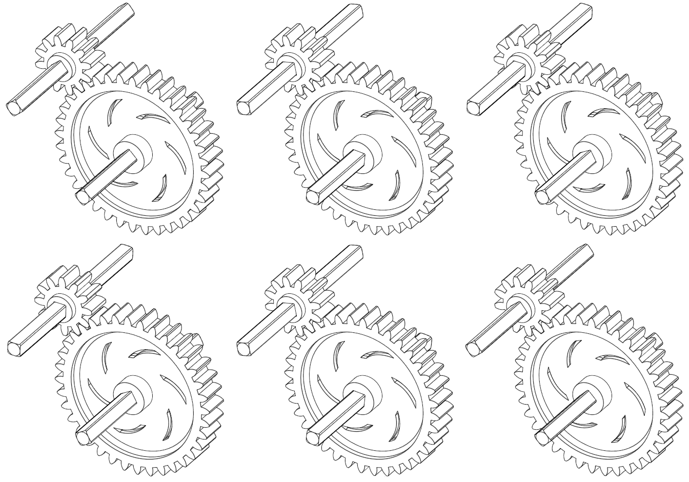
Figure 1. Coupling two gears is a symmetric relation
If the left axle is coupled with the right axle, then we can also say that the right axle is coupled with the left axle. When two axles are coupled, both axles influence each other. If you like names, this kind of relationship can be said as symmetric.
Now, look at the following set of three gears. It makes sense that if (1) we couple the left axle with the middle axle, and (2) we also couple the middle axle with the rightmost axle, then (3) the leftmost axle is now coupled with the rightmost axle. Everything is coupled together. It is a transitive relation.
Figure 2. Coupling three spur gears is a transitive relation.
What the hell, why did this bloke on the internet make these simple spur gears much more complicated? It’s not all bad*. First, you get to show off to your friends with your newly expanded vocabulary, with fancy terms like transitive and symmetry. Secondly, and this applies to many things in academia, when we give something a name, it is much easier to understand what is going and the clouds of confusion will gradually part away. Names give ideas an anchor.
*I acknowledge that sometimes making things complicated is not a good idea…
A Look At Diffs
This is a diff. It’s a bunch of bevel gears attached to a frame (called the housing). Technically, it’s better to call it a differential, not a differential gear (because it’s made up of gears). The housing is made with teeth on them so that we can “capture” the housing’s rotation by attaching another spur gear to the differential housing.
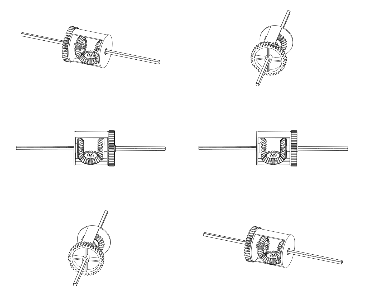
Figure 3. A set of differential gears provided in Vex Robotics.
There are three input/output parts that you can rotate in a diff, which we will call A, B, and C for the left, right, and centre piece respectively. All of these parts seem to have some effect on the other in some way similar to three spur gears…
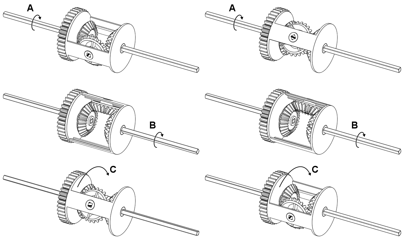
Figure 4. The three parts you can rotate in a diff.
But they’re not all directly coupled; You could stop C from moving and yet still rotate A. A reasonable question one might ask at this point is: Are they coupled in some way, but not really?
If you investigate the GIF animation with a bit more detail, if you rotate A and B, it looks like C is the average rotation of A and B! (Exclamation marks are obviously necessary here just to emphasise its importance. Besides, this observation is interesting, right? Right? No? Man you have no life.) For example, if we rotate both A and B by 360 degrees in the same direction, C also rotates 360 degrees the same direction.
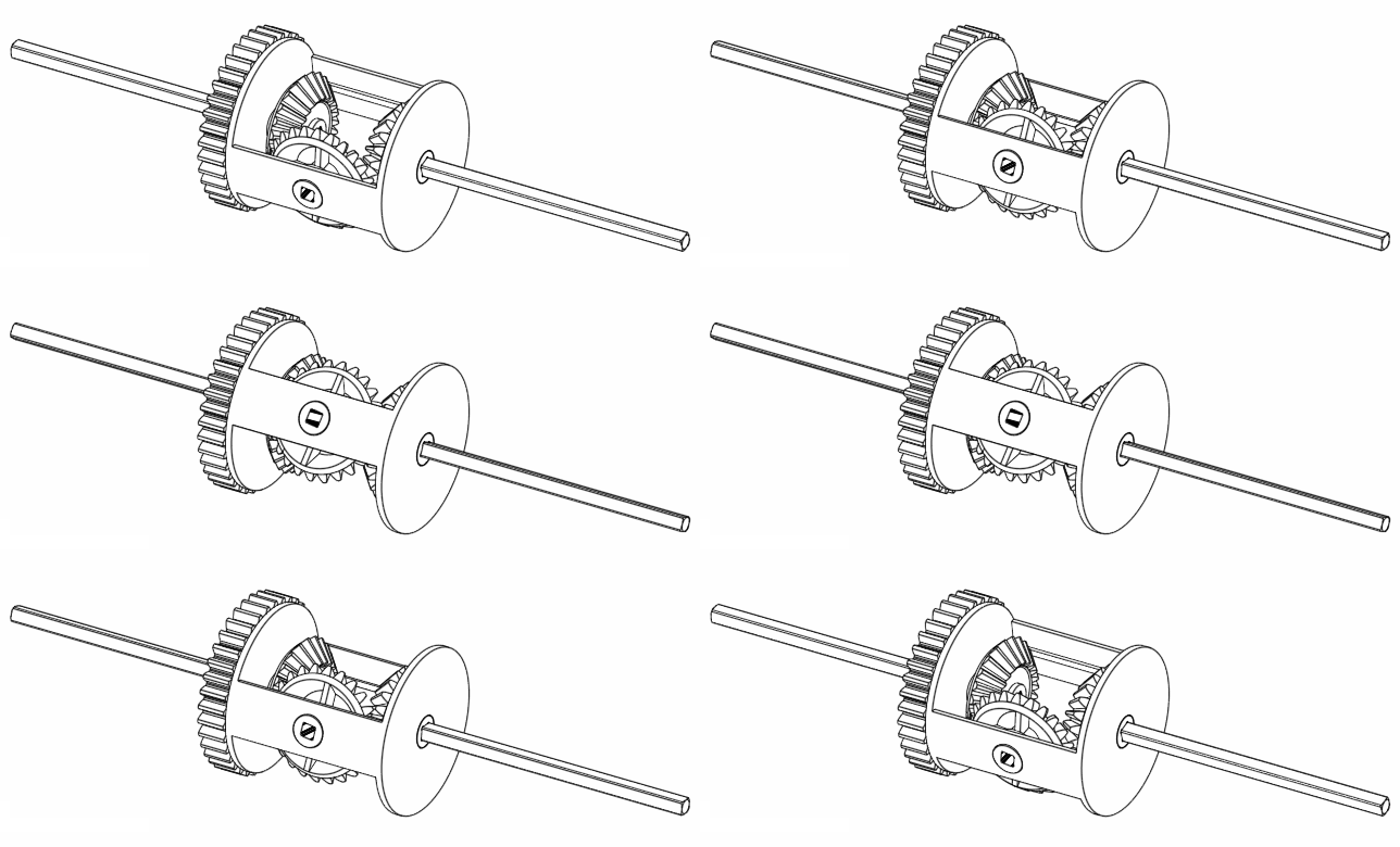
Figure 5. Rotating A and B at the same rate moves C at the same rate as well.
If we move A and B together but in a way such that B is completely opposite to A, then we find that C doesn’t move at all.
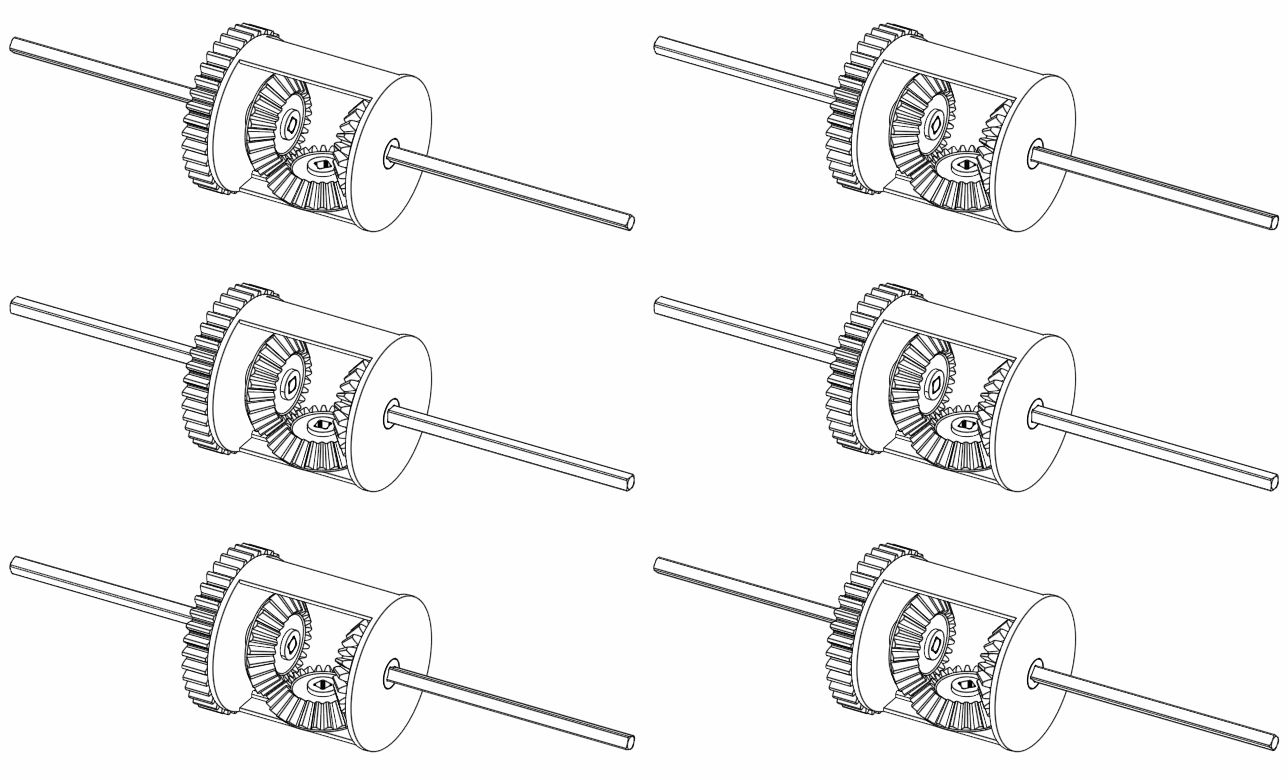
Figure 6. Rotating A and B at the opposite direction keeps C still.
Finally, if A rotates 360 degrees, but B doesn’t move, then C moves 180 degrees.
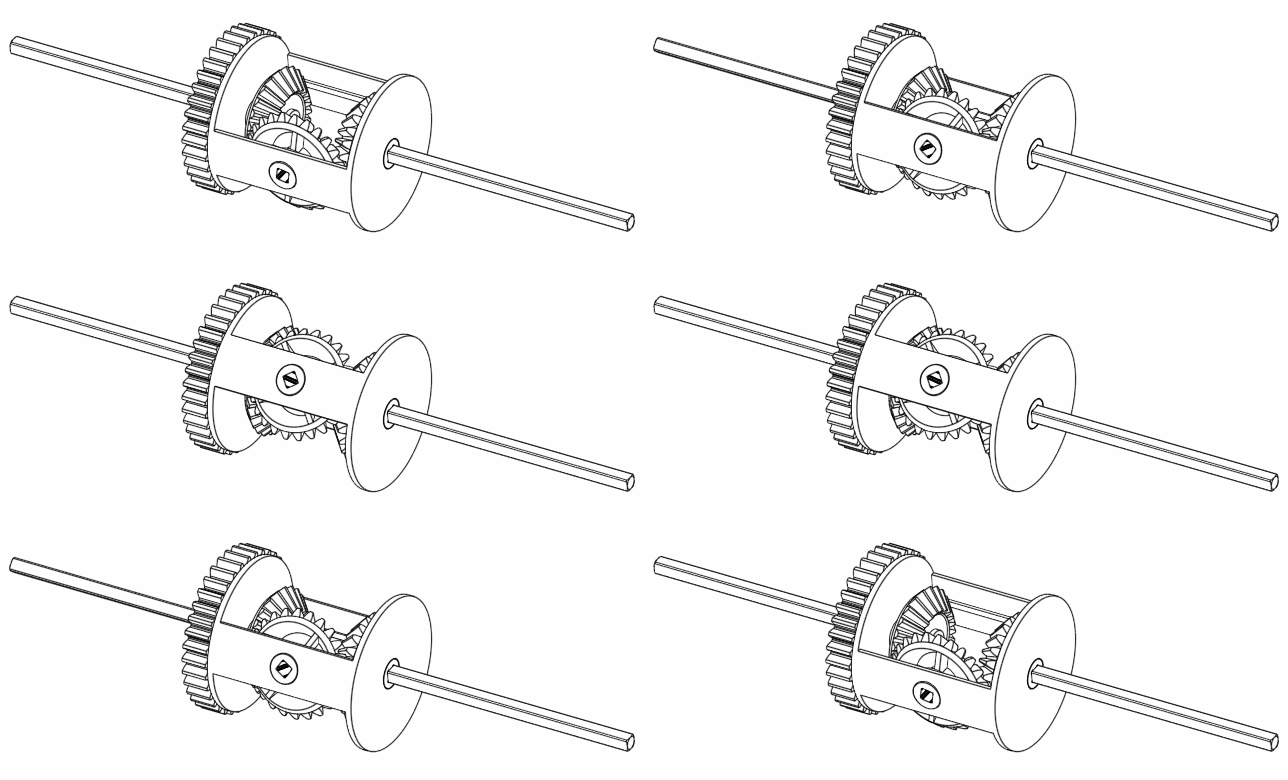
Figure 7. When keeping B still, C always rotates half the speed as A.
Hmm. Interesting. It looks like the equation $C = \frac{A+B}{2}$ is true. But why?
Thinking Outside the Box*
Imagine a box with two gears attached to the side of it like so. (*I am sincerely sorry for the shameful pun, but I have no choice.)
Figure 8. A box with two gears attached and coupled together.
You look at it and say “Welp, looks like there are two axles coupled together”. Indeed, turn one axle, and the gear causes the other axle to turn assuming that the box doesn’t move.
…assuming that the box doesn’t move…
Now I’m not sure about you, but that last phrase is begging me to ask another question: What happens if you turn the box, and treated the box itself as a thing that you can rotate (i.e. an input or output just like another axle)?
That is pretty much what a diff is: a bunch of gears inside some sort of frame, but which the frame itself can also be rotated. Another mechanism that uses this idea is the planetary gearing (aka epicyclic gearing).
There is nothing stopping us from rotating the frame. We live in a universe where there is translational symmetry and rotational symmetry built into the laws of physics. However, it’s not the “symmetry” we talked about in high school maths class, in the usual sense, where something is mirrored about, well, a mirror. The symmetry we’re talking about goes like this (it takes more than a sentence to describe). You take a purely mechanical device, such as linkage systems and gearing systems. It doesn’t matter where it is on Earth, or up in space even, and what orientation it is in, it will still behave exactly the same. It also doesn’t matter whether we are standing on the ground looking at the machine (which, by the way, is also on the ground), or whether we are on a moving train while the machine is on the ground. The machine will still behave the same kinematically because the behaviour of the machine only depends on the relative positions of the internal parts matter to the machine. We will rely on this concept in the next section to prove that what it does is what it really does.
Proof that Diffs does what it does
We will analyse three types of mechanisms which I believe are worth knowing. Looking at the figure below, the first mechanism is a linkage with three external parts A, B, and C that can slide backwards and forwards sideways. A linkage is a bunch of rods of fixed length that are attached together such that each joint is rotatable. Note that if you swap A and B around, the mechanism is exactly the same. We will now move on to the next mechanism sitting on the top right. It consists of two racks put on opposite sides of a pinion gear, and these three parts A, B and C can slide up and down. Finally, living at the bottom of the figure is our beloved diff which happens to be the subject of this post. Note that in all three mechanisms, A and B can be swapped around without changing the function of the mechanisms.
Figure 9. Here are the three types of adding machines we will analyse. If it’s hard to see what’s going on, there are some nice videos of real-life me in the real world playing with real, physical versions of these machines.
Why are we analysing all three mechanisms? Because these are all adding machines. It turns out that the very same proof/derivation works for all three of them, and that we end up with the following equation that the amount of movement of C can indeed be described by
\[C = \frac{A+B}{2}\;.\]The proof first begins with an observation.
Step 1. Note how they all act like “inverters”
Keep C still and obedient. For example, you could tape C down to the ground. What happens to B when you move A?
Figure 10.
In all three machines, B’s movement mirrors the movement of A.
Step 2. Quantify this motion
Keep C still, and let A move by $x$ units forward. Intuitively, B moves $x$ units backward, aka $(-x)$ units forward.
Figure 11.
Step 3. Move again
Keep C still, and now from the starting position, move A by $x$ units forward, followed by $y$ units backwards. Altogether, it means A has moved $(x-y)$ units forward. Because the mechanisms make B move opposite to A, altogether, B has moved $(y-x)$ units forward.
Figure 12.
Step 4. Move the entire setup
This is the fun part. Look at the machines. It doesn’t matter whether you play with them on the ground or on a moving train because B is inverted only relative to C. Therefore, you can move the entire setup by, say, $k$ units forward like so.
Figure 13.
If we calculate the total movement each piece have made, we get the following:
\[\begin{align} A &= (x-y) + k\\ B &= (y-x) + k\\ C &= k. \end{align}\]In fact, we can replace $k$ with anything we want. On the previous setup we ended up with in step 3, let’s see what happens if we move the entire setup by $k = x+y$. In other words, we move the setup by $x$ first, then an additional $y$ units forward.
Figure 14. There’s a lot going on in the diagram - more than I hoped. Here’s what each thing means. The thin dotted arrows show the movement that was previously applied in step 3. The thick solid arrows show the movement we’re going to make in this step. Note how the thick arrows are all the same size and direction inside each mechanism. This is because we’re moving the entire setup.
We have reached the final part of this casual proof. Calculating the final positions of each piece gives us
\[\begin{align} A &= (x-y) + (x+y) = 2x\\ B &= (y-x) + (x+y) = 2y\\ C &= x + y. \end{align}\]Rearranging completes the proof/derivation.
\[C=x+y = \frac{A+B}{2}.\]Real life footage of ‘diff and friends’ at their natural habitat
Tip: turn up the volume for these videos.
Video 1. Playing around with the linkage adder.
The one that started it all, introducing you to the linkage adder. When I built this in 2013, I was actually trying to create a subtracting machine instead. It never ceases to amaze me how different design intents lead to bizarrely accurate designs of other things that we don’t know about until many years later. Note that I included an additional linkage system that multiplies the output movement by two so that the output is actually the addition of the inputs, not just their average. When the young and naive version of me built this linkage, I thought that it was needed to “correct” the movement.
Video 2. Playing around with a rack and pinion adder.
Video 3. Here I assemble a Lego differential and play around with it.
So Why do Diffs Take This Form?
Why are we using bevel gears inside a housing, and not using linkage adders or rack and pinions?
Answer: diffs can go round and round and round and round and round and…
Where do we go from here
I hope someone will enjoy this post. In the next couple of posts, we will look at some fun applications of these differentials (fun by my standards anyway). We will also look at ways to further model the differential in terms of torque and energy transfers. In other words,
Stay tuned for the next episode of The-Random-Bloke-On-The-Internet-Talking-About-Stuff.
Yes.
Geoffrey Kolbe
12 Sep, 20Ernest Wong
16 Sep, 20